


Hot Online
400-027-6688
Product profiles
1, the pressure relief equipment in accordance with the Ministry of construction of the Republic of China in August 1996 [1996]108, the text of the development and design of a new type of fire pressure relief equipment, while in line with the provisions of 98S205 (original 98S176).
2,The high fire water tank two, the pressure stabilizing device arranged to solve the temporary high pressure fire water supply system, the installation height of the system can not meet the most unfavorable point when the hydrostatic pressure facilities should be used for the preparation of the design requirements, pressure regulator equipment fire special (hereinafter referred to as the "equipment").
3, this equipment is suitable for multi-storey and high-rise construction with fire hydrant system booster facility requirements and wet automatic sprinkler system and fire water supply, water supply system.
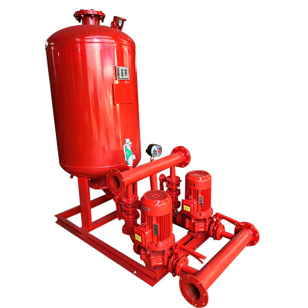
4, "equipment" by the diaphragm pressure tank, water pump, electric control box, instrument, pipe accessories, etc..
5, this equipment complies with the "Ji civil code for fire protection design of buildings" (referred to as "high regulation") and "GB50045-95", CECS76:95 pneumatic water supply design specification provisions of technical parameter design.
technical conditions
1, WXQ regulator tank working pressure: 0.6MPa, 1.0MPa, 1.6MPa.
2, WXQ pressure tank fire storage capacity is greater than: 150L, 300L, 450L.
3, WXQ diaphragm tank of water capacity is greater than 50L.
4, WXQ diaphragm pressure tank buffer water capacity backlog difference is 0.02~0.03MPa, the water capacity of the backlog is poor 0.05~0.06MPa.
5, working pressure ratio: a b value of 0.6~40 C
Applicable conditions
1, fire hydrant system: water flow per 2.5L/S, 5L/S, 7m, 10m for the full water column length, 13m.
2, automatic sprinkler system: each nozzle flow 1.0L/S, nozzle pressure 0.1MPa.
3, the environmental temperature of the equipment should be 5 ~40.
Working principle
1, so that the fire water supply system is the most unfavorable point to maintain the fire pressure;
2, the WXQ diaphragm pressure tank storage always have 30 seconds. The fire water pressure tank set by P1, P2, Ps1, Ps2 operating pressure control, pump running, and the voltage boosting power
Can.P1 for the most vulnerable point of the fire pressure (MPa), P2 for the fire pump start pressure (MPa), Ps1 for the fire pump start pressure (MPa), Ps2 for GDL pressure pump stop pump pressure MPa
Operation control process
According to the calculation of the automatic sprinkler system or fire hydrant pressure in P1 system the most unfavorable point required, as inflation pressure pressure tank through the calculation of the option set reports of pressure tank specification and a B, obtained P2, and set the
Ps1=P2+ (0.02~0.03)
Ps2=Ps1+ (0.05+0.06)
Usually if there is leakage when the pipeline system pressure control *, XBD-L fire pump continuous replenishment regulator, in Ps1, Ps2 (start and stop) repeated operation. If there is a fire, a lot of water pipeline system, pressure drop caused by Ps1 (Ps1, Ps2), to P2, issued a warning signal, immediately start the fire pump (manual or automatic startup is determined by design), XBD-L vertical single stage fire pump start, automatic stop XBD-ISG fire pump, until the XBD-LG vertical multistage fire pump stop operation manual recovery "control equipment".
classification
According to the "equipment" set position: toploading (I) and bottom (II);
According to the pressure tank settings: vertical (L) and horizontal (with W);
According to the equipment for the fire water supply system: fire water system (X)
Automatic sprinkler system (expressed in Z)
Fire hydrant and automatic sprinkler system used to hydrate (XZ).
P1 calculation
P1 refers to the fire water supply system is the most unfavorable point fire hydrant or automatic sprinkler head for fire pressure, is the "equipment" operation of the minimum working pressure, is the basic data of this equipment should be mastered.
1, the "equipment" in the bottom water from the pool, calculation formula of fire hydrant system:
P1=H1+H2+H3+H4 (mH2O);
H1 from the pool to the lowest level. The most unfavorable hydrant geometric height (mH2O);
The sum of the local pressure loss along the H2 pipeline system (mH2O);
The pressure loss of H3 hose and fire hydrant itself (mH2O);
H4 spray gun body full water column length required pressure (mH2O);
2, the "equipment" in the high water tank never box from the irrigation water, and the most unfavorable point fire hydrant below "equipment", calculation formula of fire hydrant system
P1=H3+H4 (mH2O)
3, the "equipment" at the bottom of the suction from the pool, automatic sprinkler system calculation formula:
P1= H+Ho+Hr+Z (mH2O).
Sigma H - automatic water pipeline to the most unfavorable point along the nozzle and the local pressure loss and (mH2O);
HO - the most unfavorable point of sprinkler operating pressure (mH2O) >
Hr - local head loss of alarm valve (mH2O) >
Z - Geometric height (mH2O) between the lowest point of the nozzle and the lowest water level of the pool (or water supply pipe)
4, the "equipment" is located in the high water tank from the water tank from the water, and the most unfavorable point when the sprinkler is lower than the equipment, automatic sprinkler system calculation formula:
P1= H+Ho+Hr+Z (mH2O) > 5, when the air pressure tank and the water pump are respectively arranged in other places, P1 shall be calculated.
Several notes
1, the "equipment" booster standard: P1 for the "equipment" minimum working pressure, its value should meet the fire water supply system of the most unfavorable point of the fire pressure. If the fire hydrant water supply system, must satisfy the most unfavorable point fire hydrant spray gun body full water column length, not only to meet the hydrostatic pressure 0.07MPa or 0.15MPa standard booster.
2, the calculation of P1, the pipeline system used along the process and the local loss of the flow, should be early fire to water, such as fire hydrant system is two X 5 fire hydrant flow rate of 2 (L/S) =10 (L/S) or 2 x 2.5 (L/S) =5 (L/S); automatic sprinkler system is 5 a nozzle flow, generally use 5 x 1 (L/S) =5 (L/S).
3, the "equipment" of the main components: reports of pressure tank fire water supply system should have the required storage water volume, water volume and water buffer volume regulator, according to the a b value between the diameter and the specifications. For the pressure tank volume water hydrant water supply system is not less than 300L; for not less than 150L of sprinkler pressure tank water storage capacity of the system; for not less than 450L fire hydrant and automatic sprinkler pressure tank water volume system.
4, the "equipment" with ISGD pump two units (with a prepared). The most stable flow rate should be within 3 minutes, to make up the actual pressure of the WXQ diaphragm pressure tank water flow volume. The head of the pump should be in the (PS1+PS2) /2, the curve of the pump area. The "equipment" function is to solve the initial stage of the fire, that is, before the start of the main fire pump, to ensure adequate fire pressure 30S water storage for the initial fire ball until the full load of the fire pump.
The system can use a set of pressure stabilizing equipment 5, fire hydrant system and automatic sprinkler. Fire when the pressure tank pressure drops to P2, the fire control center or other signal to the fire hydrant pump according to the fire hydrant system or automatic sprinkler system were issued, after the confirmation of the fire hydrant pump or automatic spray pump start.
6, the fire hydrant water supply system by using the "equipment" is better than the underneath type. Overhead type pump with low P1 for Yang program, hose and lance resistance loss and spray body length required to enrich the water column pressure and pressure tank, air pressure, low pressure, steel saving and high operation cost.
Electrical performance
1, the equipment control system with automatic and manual functions, and with the fire control center or fire pump network.
2, two sets of water pump with a standby, turn the work of automatic switching, alternating operation.
3, the usual fire pipe in a high pressure condition, and maintain a certain amount of water stored in the tank, due to leakage and other reasons, the system pressure down to Ps1 No. 1 pump automatic start, stop the pump pressure rose to Ps2, the pressure and pressure drop again next time next to Ps1, automatically start the pump 2, so alternative operation. The system pressure is always maintained at between Ps1 and Ps2.
4, a fire occurred, the system pressure decreased from Ps1 to Ps2 to start the fire pump output signal and the sound and light alarm when the fire pump start control power back to the signal to cut off the pump, followed by the manual recovery control function.
5, control system of ad hoc maintenance state, namely operation as No. 1 pump failure, can be easily transferred to the pump No. 2, No. 2, if the pump fails, can be converted to the pump No. 1 make a water pump in the maintenance of the "equipment" is still able to operate normally.
6, the electronic control box size, electrical control principle and the composition of the main components of the company's cable guide automatic control instructions.
Other description
1, diaphragm type pressure tank according to GB 91SS852 standard atlas manufacturing.
2, the pipe seamless steel pipe, hot dip galvanized steel, galvanized seamless steel pipe.
3, "equipment" using integrated series of integral steel support. This atlas is according to the form of bearing diaphragm pneumatic tank skirt drawing, can also be used to support.
4, the "equipment" for the overhead type isolation measures should be set up. The pump unit must install the rubber isolation pad in process to prevent pump dumping measures recorded pump unit vibration isolator is installed, installed in the pump inlet and outlet pipes, fittings and accessories, must be taken to prevent the pump unit tilt measures to ensure the safety of construction.
5, pressure tank water discharging device is provided with a safety valve, set in the pipeline system, remote pressure gauge and other accessories.
6, the "equipment" peripheral drainage facilities, easy maintenance, discharge or exclusion for Water Leakage.
7, the equipment and the wall or other equipment should be left between the distance, generally not less than 700mm.
8, "equipment" should carry out the overall water pressure test, hydraulic pressure strength test and tightness test, according to the relevant provisions of the implementation of the requirements.
9, the "equipment" connecting piping, fittings, pressure tank and other surface shall be brushed with antirust paint brush two, non-toxic anticorrosive coating surface pressure tank.
10, water pumps, motors, piping installation technical requirements in accordance with the relevant technical requirements.
number | Pressure stabilizing device | Fire pressureMpa | Vertical diaphragm pressure tank | Equipped with water pump | Equipment running weightKg | Operating pressureMpa | Regulated water volumeL | ||||
Model | Working pressure ratio | Fire storage capacity(L) | Model | ||||||||
Calibration volume | Actual volume | ||||||||||
1 | ZW(L)-I-X-7 | 0.1 | SQL800*0.6 | 0.60 | 300 | 319 | 25LG3-10*4 1.5KW | 1452 | P1=0.10 Ps1=0.26 | 54 | |
2 | ZW(L)-I-Z-10 | 0.16 | SQL800*0.6 | 0.80 | 150 | 159 | 25LG3-10*4 1.5KW | 1428 | P1=0.16 Ps1=0.26 | 70 | |
3 | ZW(L)-I-X-10 | 0.16 | SQL800*0.6 | 0.60 | 300 | 319 | 25LG3-10*5 1.5KW | 1474 | P1=0.16 Ps1=0.36 | 52 | |
4 | ZW(L)-I-X-13 | 0.22 | SQL1000*0.6 | 0.76 | 300 | 329 | 25LG3-10*4 1.5KW | 2312 | P1=0.22 Ps1=0.35 | 97 | |
5 | ZW(L)-XZ-10 | 0.16 | SQL1000*0.6 | 0.65 | 450 | 480 | 25LG3-10*4 1.5KW | 2312 | P1=0.16 Ps1=0.33 | 86 | |
6 | ZW(L)-XZ-13 | 0.22 | SQL1000*0.6 | 0.67 | 450 | 452 | 25LG3-10*5 1.5KW | 2312 | P1=0.22 Ps1=0.41 | 80 | |
7 | ZW(L)-II-Z- | A | 0.22-0.38 | SQL800*0.6 | 0.80 | 150 | 159 | 25LG3-10*6 2.2KW | 1452 | P1=0.38 Ps1=0.53 | 61 |
8 | ZW(L)-II-Z- | B | 0.38-0.50 | SQL800*1.0 | 0.80 | 150 | 159 | 25LG3-10*8 2.2KW | 1513 | P1=0.50 Ps1=0.68 | 51 |
9 | ZW(L)-II-Z- | C | 0.50-0.65 | SQL1000*1.6 | 0.85 | 150 | 206 | 25LG3-10*9 2.2KW | 1653 | P1=0.65 Ps1=0.81 | 59 |
10 | ZW(L)-II-Z- | D | 0.65-0.85 | SQL1000*1.6 | 0.85 | 150 | 206 | 25LG3-10*11 3KW | 1701 | P1=0.85 Ps1=1.04 | 57 |
11 | ZW(L)-II-Z- | E | 0.85-1.00 | SQL1000*1.6 | 0.85 | 150 | 206 | 25LG3-10*13 4KW | 1709 | P1=1.00 Ps1=1.21 | 50 |
number | Pressure stabilizing device | Fire pressureMpa | Vertical diaphragm pressure tank | Equipped with water pump | 设备运行重量Kg | Operating pressureMpa | Regulated water volumeL | ||||
Model | Working pressure ratio | Fire storage capacity(L) | Model | ||||||||
Calibration volume | Actual volume | ||||||||||
12 | ZW(L)-II-X- | A | 0.22-0.38 | SQL1000*0.6 | 0.78 | 300 | 302 | 25LG3-10*6 2.2KW | 2344 | P1=0.38 Ps1=0.55 | 72 |
13 | ZW(L)-II-X- | B | 0.38-0.50 | SQL1000*1.0 | 0.78 | 300 | 302 | 25LG3-10*8 2.2KW | 2494 | P1=0.50 Ps1=0.70 | 61 |
14 | ZW(L)-II-X- | C | 0.50-0.65 | SQL1000*1.6 | 0.78 | 300 | 302 | 25LG3-10*10 3KW | 2689 | P1=0.65 Ps1=0.88 | 51 |
15 | ZW(L)-II-X- | D | 0.65-0.85 | SQL1000*1.6 | 0.85 | 300 | 355 | 25LG3-10*13 4KW | 2703 | P1=0.85 Ps1=1.05 | 82 |
16 | ZW(L)-II-X- | E | 0.85-1.00 | SQL1000*1.6 | 0.88 | 300 | 355 | 25LG3-10*15 4KW | 2730 | P1=1.00 Ps1=1.21 | 73 |
17 | ZW(L)-II-XZ- | A | 0.22-0.38 | SQL1200*0.6 | 0.80 | 450 | 474 | 25LG3-10*6 2.2KW | 3641 | P1=0.38 Ps1=0.53 | 133 |
18 | ZW(L)-II-XZ- | B | 0.38-0.50 | SQL1200*1.0 | 0.80 | 450 | 474 | 25LG3-10*8 2.2KW | 3947 | P1=0.50 Ps1=0.68 | 110 |
19 | ZW(L)-II-XZ- | C | 0.50-0.65 | SQL1200*1.6 | 0.80 | 450 | 474 | 25LG3-10*10 3KW | 3961 | P1=0.65 Ps1=0.87 | 90 |
20 | ZW(L)-II-XZ- | D | 0.65-0.85 | SQL1200*1.6 | 0.80 | 450 | 474 | 25LG3-10*12 4KW | 4124 | P1=0.85 Ps1=1.12 | 73 |
21 | ZW(L)-II-XZ- | E | 0.85-1.00 | SQL1200*1.6 | 0.80 | 450 | 474 | 25LG3-10*14 4KW | 4156 | P1=1.00 Ps1=1.30 | 64 |
Note: 1. In the operating pressure of symbols: the gas pressure P1---- pressure tank (required fire pressure) (MPa) |
number | Name |
1 | Air pressure tank |
2 | Pressure gauge |
3 | Check valve |
number | Name |
6 | Water pump |
5 | Rubber flexible joint |
6 | Water pump |
Air pressure tankModel | Φ | H | A | A1 | L | L1 |
Φ800 | 800 | 2480 | 800 | 760 | 1400 | 1200 |
Φ1000 | 1000 | 2800 | 1000 | 960 | 1600 | 1400 |
Φ1200 | 1200 | 3210 | 1200 | 1160 | 1800 | 1600 |
Hot Online
400-027-6688
Copyright (C) 2009-2017 Shanghai Beiyang Pump Manufacturing Co., Ltd. All Rights Reserved